
Interpolatable Colour Inversion
I was recently working on porting a shader I wrote to a friend's video framework so it can be used as a visualizer for a music compilation. This had me adding many tunable parameters that can be tweaked on a per-song basis using sliders. The more sliders, the more looks we can produce, and therefore the more songs we can cover with the same shader.
One surprisingly useful slider is colour inversion. This is a very common image operation which is even available in MS Paint. The operation goes as follows: assuming your colours range between 0 and 1, then each pixel value x just gets mapped to (1-x).
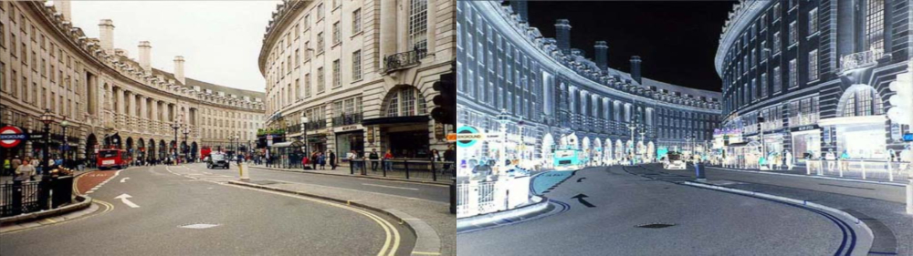
A sample image with its inversion.
I implemented inversion as one of the sliders, whose value ranges between 0 and 1, with the following glsl code:
FragColor.xyz = mix(FragColor.xyz, 1.-FragColor.xyz, invertSlider);
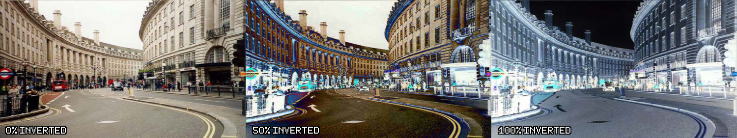
However, there is a subtle problem with an "invert" slider when implemented in this way. In the visualizer framework, the transition from one song to another is done by smoothly interpolating all the tunable parameters to their new values. This can get ugly when you interpolate from 0% inverted to 100% inverted:
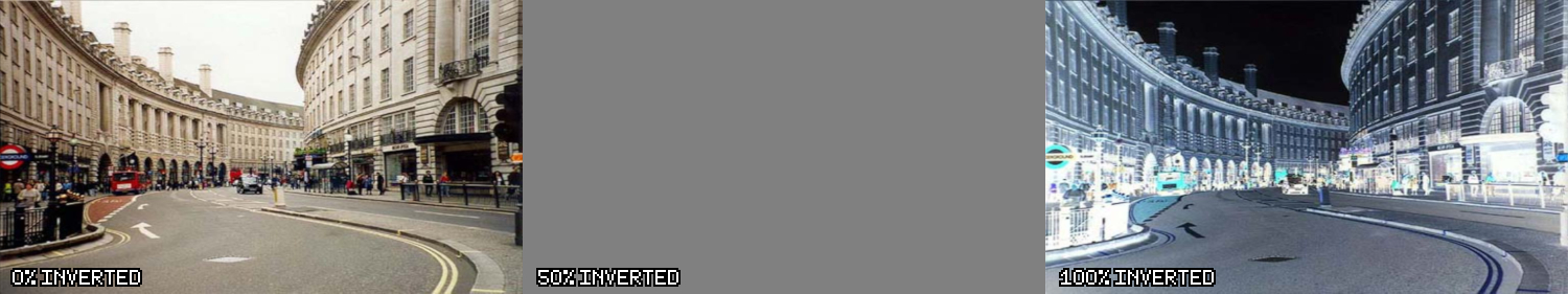
At 50%, the image disappears!
This means that every time we transition between a song whose shader isn't inverted to one that is, the whole screen will have to transition through flat grey. That's not very nice at all.
The problem becomes clear when you visualize graphically what happens to each colour under the transformation. Every possible input colour value gets mapped to a different output value. This mapping changes depending on the value of the "invert" slider. If you've ever used "curves" in Photoshop or GNU IMP, then this kind of graph should be familiar:
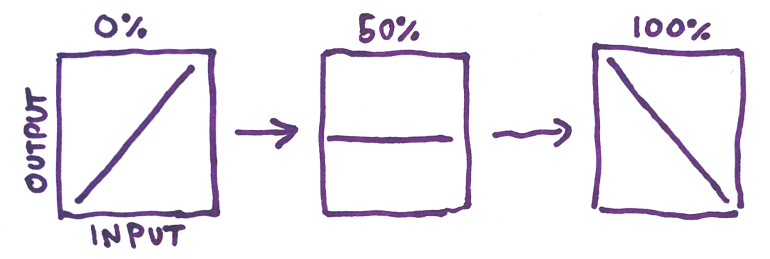
You can see that at 50%, all pixels get mapped to the same colour: grey. This is a consequence of our "mix" function—at 0.5 the formula simplifies like so: x*0.5 + (1-x)*0.5 = x*0.5 - x*0.5 + 0.5 = 0.5. If we want to avoid the grey, we need to come up with a better way to interpolate between non-inverted to inverted.
There are probably many equally sensible ways to go about this, but the idea I came up with is to aim for a particular function to appear at 50%:
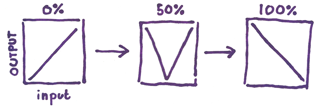
The function in the middle is often referred to in image editing software as the "solarize" filter. The name "solarize" comes from a photochemical process that causes bright tones to "turn around" and become dark again. I've decided to call this kind of invert Solar Invert, because at 50% it does the solarization operation.
After much thinking, I figured out how to implement this 2-dimensional function (one dimension is the colour, the second is the level of the invert slider). Below is the implementation in GLSL:
vec3 solar_invert(vec3 color, float x) {
    float st = 1.-step(.5, x);
    return abs((color-st)*(2.*x+4.*st-3.)+1.);
}

//how to use the function:
FragColor.xyz = solar_invert(FragColor.xyz, invertSlider);
Here's how it looks with the "london" sample image from before:
At 50%, the image actually looks interesting!
One nice benefit of doing the inversion this way is that, unlike normal inversion, the in-between values for the inversion slider actually look interesting, and can therefore contribute to the "look" for a particular song's visualizer, adding another dimension of tuneability to this shader.
Solar inversion actually has two types. I'll call the one I showed so far V-type, because at 50% the graph makes a "V" shape. The second type I'll call A-type, because the graph makes an A shape. You can get A-type by doing:
//A-type solar invert:
FragColor.xyz = 1.-solar_invert(1.-FragColor.xyz, invertSlider);
To better visualize the function, I've also implemented it in Desmos so you can see how the pixel value mapping as the invert slider (called "t" here) changes:
Finally, here's a shadertoy implementation. The top band is normal invert, the second band is A-type solar invert, and the last band is V-type solar invert. You can change the level of inversion by clicking and moving your mouse from the left to the right.
← Back